

Oil Centrifuge Machine
Oil Centrifuge Machine
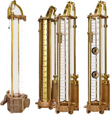
download product catalogueThe CENTRIFUGE MACHINE (OCM) is designed to test the viscosity of petroleum products.
OIL CENTRIFUGE MACHINE FEATURES
Portable, lightweight, with durable aluminum body.
Self lubricating.
Fast worm gear drive.
Built-in C-clamp for easy mounting
Self lubricating
Three available Pyrex tube types: : 1. Finger tube, 12.5 ML | Short cone, 100 ML 200% | Pear shaped cone, 100 ML 200%.
-
Oil Centrifuge Machine Parts
Part# Description OC103 Wood Handle 
OC106 Clamp Knob Screw 
OC110A Crank Shaft 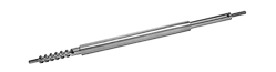
OC110B Worm Shaft 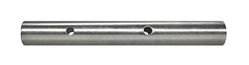
OC111 Gear, Brass 
OC113A Body 
OC1140 Cover 
OC116 Crank Arm 
– Head Assembly – Tube (2 Req.) – Shield (2 Req.)
Oil Thief
Oil Thief
download product catalogueThe OIL THIEF (OT, or OTIV for the Internal Valve unit), is a simple device that is utilized to collect accurate crude oil samples. Their lengths can be customized to suit your sampling needs. Sample cocks, also known as drain valves, can also be installed to test the different levels of your sample.
OIL THIEF FEATURES
Available in Slide Valve or Internal Valve.
Standard barrel lengths are 12, 14, 16, 18, and 24 inches. (Custom barrel lengths are available upon request.
Barrels are available in plastic, Pyrex, or polished brass.
Plastic and brass barrels can be installed with sample cocks upon request.
Lowering devices available – your choice of either brass chain or braided rope with fittings.
-
SNAP CLOSURE
- With the valve closed, make sure the trip rod is pushed fully into its sleeve, then lock the trip rod in this position by tightening the thumbscrew in the clutch top.
- Slide Valve Thief: Open the valve by pulling it outward until the clutch pin holds it open.
Internal Valve Thief: Open the valve by pushing the lever down until the cock pin holds it open. - Put the bail assembly hook into the slot at the top of the trip rod sleeve.
- Slowly lower the oil thief to the desired level in the tank.
- Give the lowering line an abrupt upward jerk. This should trip the valve closed, making the sample ready for retrieval from the tank.
-
TANK BOTTOM BUMP CLOSURE
- Set the trip rod so its bottom end is at least 1/4 inch below bottom of oil thief, or extended to the desired sample height from bottom of tank.
- Slide Valve Thief:Lock the trip rod securely in set position by tightening the thumbscrew in the clutch top.
Internal Valve Thief:Lock the trip rod securely in set position by tightening the thumbscrew in the valve cock. - Open the valve.
- Lower the oil thief in a continuous motion until it bumps the tank bottom and trips the valve closed. Sample is now ready for retrieval.
-
MAINTENANCE
*All repairs must be sent back to factory for warranty to remain effective. -
Oil Thief Parts
Part# Description QTY. OT OTIV OT & OTIV OT OTIV O0001 O0001-IV Body 

O0002 O0002-IV Top Ring 

O0003 O0003-IV Valve 

O0003A O0003AIV O-Ring Valve Sea 

– – Trip Rod – – Trip Rod Sleeve O0011A O0011A Bail Assy 
O0021 n/a Hanger 
n/a – – Plastic Barrel M1012 M1012 Cork Gasket 
X0T09 X0T09 Brass Thumbscrew 
X0T17 X0T29 Brass Acorn Nut 

Manifold Primer
Manifold Primer
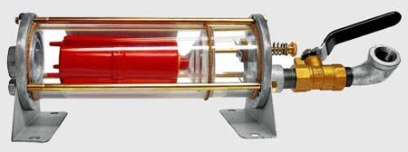
download product catalogueTHEMANIFOLD PRIMER/Water Trap (MP) is a device positioned between a water pump being primed and a source of vacuum pulling the water. It is designed to stop water flow when water reaches it. As a manifold primer it is used when the vacuum source is the intake manifold of a multiple-cylinder gasoline or LP gas engine, or brake booster of a vehicle. As a water trap it is used when the vacuum source is a vacuum pump. The manifold primer/water trap utilizes a mechanical float valve that stops airflow as water enters the unit, thus “trapping” and preventing the water from continuing past it. MP1000 – Has 3/8 NPT flow ports, IN at bottom and OUT at top. Mounting requires four 1/4″
bolts or screws. Water drains from the unit through the priming line.
MP2000 – Has 1/2 NPT IN and OUT flow ports on the bottom. Mounting requires two 1/4″ bolts or screws. Water drains from the unit through an umbrella valve on the bottom.
MANIFOLD PRIMER FEATURES
Can be mounted on any surface.
Use on multiple cylinder gasoline or LPG engines.
Durable clear housing allows operator to observe its functioning.
Brass ball valve included.
-
INSTALLATION
- Mount the unit in position so that the float mechanism moves vertically and is at an elevation above the pump priming port.
- Use noncollapsible hose to connect the unit OUT port to the vacuum source, for example a tee fitting spliced into the vacuum line.
- Use noncollapsible hose to connect the unit IN port to the pump priming port, with the provided ball valve in between.
-
OPERATION
- Close the priming line ball valve.
- Close the pump discharge valve to prevent air being drawn through the discharge.
- Start the vacuum source.
- Open the priming line ball valve.
- When water enters unit, close priming line ball valve. (Water entering unit indicates pump is primed.)
- Start the pump and open the pump discharge valve.
- Stop the vacuum source then allow the water to drain from the unit
*NOTE: If water does not flow from discharge, turn your pump OFF and repeat steps 2 through 5. When pump is discharging properly the priming line may be disconnected from primer and the engine providing vacuum turned OFF.
-
MAINTENANCE
- Chamber housing should be kept clean in order to observe the float valve.
*If necessary, remove the unit and flush with water or a mild soap solution.
*Do not use any harsh cleanser or chemicals to clean the unit.- Use only soap and water to clean plastic parts.
- Do not tighten tie bolts or plastic dome more than necessary to provide seal.
- Keep the priming line ball valve closed when manifold primer/water trap not in use.
-
Manifold Primer – Parts
STANDARD PARTS PART# PART DESCRIPTION M1001 
Top Cover Assembly(See Lower Chart) M1002 
Lower Cover M1003 
Lower Housing M1004 
Upper Housing M1005 
Mounting Bracket (2 Req.) M1008 
Float Assembly (See Upper Right Chart) M1010 
Tie Bolt (3 Req.) M1012 
Cork Gasket (3 Req.) M1014 
Angle Valve (See Bottom Chart) TOP COVER ASSEMBLY – # M1001 PART# PART DESCRIPTION M1006 
Top Cover Only M1007 
Valve Stem Assembly M0051 
Ball w/ Pin Assembly ANGLE VALVE ASSEMBLY – #M1014NEW PART# DESCRIPTION PART E0334 Brass Cock Valve 
X0E17 Close Nipple 
X0P67 ³/8″ Street Elbow 
FLOAT ASSEMBLY – #M1008 PART# PART DESCRIPTION M1009 
Suction Cup M1013 
Float Only 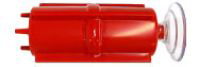
BALL ASSEMBLY – #M0051 M1018 
Rubber Ball X0M62 
Cotter Pin VALVE STEM ASSEMBLY – #M1007 PART# PART DESCRIPTION M1011 
Cork Seal Washer M1019 
Stainless Steel Spring M1021 
Stainless Steel Washer (2 Req.) M1022 
Plunger Rod X0M61 
Retainer Clip X0M63 ³/32 x 1″ Cotter Pin ACCESSORIES PART # DESCRIPTION X0D03 ¼-20″ Hex Nut (3 Req.)
Power Primer
Power Primer
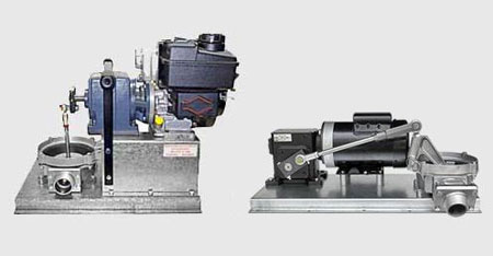
download product catalogueTHE POWER PRIMER is built for fast and efficient priming in pump installations with high suction lifts or extra suction lines. Our motorized line of power primers come in AC, DC or gasoline models and work well for a variety of applications. They are ideal for large, diesel-powered irrigation pumps.
POWER PRIMER PUMP FEATURES
Vacuum Pump self-lubricating vanes make maintenance easier.
Steel and cast iron construction handle the heaviest service duties.
Vacuum Pump dual fan guards meet OSHA’s safety requirements.
Clear, plastic water trap housing indicates when priming is completed.
AC single phase model has 8’ electrical cord with switch.
Solid base provides a sturdy mounting platform.
Standard 1/2″ NPT vacuum connection.
-
INSTALLATION & OPERATION
- Mount the Power Primer securely to a plate on the engine or centrifugal pump.
- Primer should be high enough to allow water to drain back into pump suction line.
- Position the unit to provide easy access to lubricators, filters and mufflers.
- Install hand valve between the power primer and the volute of the pump.
- To start priming, open priming line valve and turn primer on.
- Watch for water to appear in water trap.
- When water appears in trap, turn pump OFF and CLOSE priming line.
-
MAINTENANCE
- Vacuum Pump requires occasional flushing. Remove pressure gauge and run 1/4 cup of flushing solvent (Gast AH 225 or equivalent) through pump.
- Brief warm-up may be required for pump to produce a vacuum.
- Perform initial inspection after 500 hours.
- Use engine oil with viscosity of SAE10 when refilling oiler.
- Clean or replace air filters as needed.
- Keep water trap clear of debris.
-
SAFETY & RECOMMENDATIONS
- Make sure that electrical connection is grounded.
- Do not operate primer without drive guard.
-
Power Primer Pump – Parts
STANDARD PARTS PART# PART DESCRIPTION E0333 
Vacuum Gauge P0003 
Vacuum Pump (See Chart Below) MP2000 
Water Trap P0005 
Galvanized Tee P0015 Lower Base (*Honda units will use part# P0013) P0018 
Drive Coupling Guard P2019 
½” NPT Pipe Union X0P50 
½” MPT x ⅜” FPT
Steel Hex BushingX0P67 
⅜” NPT
Street ElbowADDITIONAL PARTS FOR PP35AC PART# PART DESCRIPTION P0011 
8′ Electric Cord ADDITIONAL PARTS FOR PP35DC PART# PART DESCRIPTION P0020 
Battery Disconnect Switch Lever, 12V, 100amp AVAILABLE MOTORS FOR PP SERIES PART# DESCRIPTION CURR. P5001 5.5 HP, Gas Engine w/ Gear Red., Honda N/A P5004 1 HP, 1 Phase AC P5004-1 1 HP, 3 Phase AC P5009 1 HP, 12 Volt DC Direct, 1750 RPM DC P5015 1 HP, 24 Volt DC PP35DC – MOTOR KIT PART# DESCRIPTION P0010 Pulley for 1065 Vacuum Pump 3-½ x ½ P0012-1 FHT Belt ½” x 30″ P5009 12 Volt DC Direct, 1HP, 1725 RPM
Hand Diaphragm Primer
Hand Diaphragm Primer
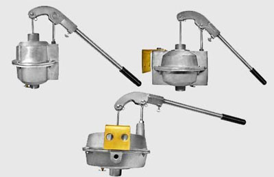
download product catalogueTHE HAND DIAPHRAGM PRIMER IS AN AIR PUMP(DP) that creates vacuum in a centrifugal pump priming line and pulls water up into the pump to prime it. The DP has a flapper check valve in the diaphragm and a disk check valve at the bottom of the unit. Air flows through the bottom check valve on the diaphragm up stroke then through the diaphragm valve on the down stroke. Diaphragm is actuated through a connecting rod eyebolt attached to a fulcrum handle bracket.
Compatible products : Centrifugal Pumps are ideal for hand diaphragm primers.
Common names : hand pump primer, suction lift primer, portable primer, permanent primer, hand pump, handy pump, irrigation water pump, handy pumper.
HAND DIAPHRAGM PRIMER FEATURES
Lightweight aluminum alloy body
Easily mounted on most centrifugal pumps.
Tough and durable rubber diaphragm.
Units have a drain valve.
-
INSTALLATION & OPERATION OF HAND DIAPHRAGM PRIMER PUMP
- Attach mounting bracket to centrifugal pump or skid.
- Use non-collapsible hose or flexible tubing to connect primer suction inlet to pump.
- Install cut-off valve between the primer suction inlet and pump.
- Close cut-off valve immediately after priming.
- Make sure primer drain valve is closed.
- A cut-off valve should be used at the pump discharge to prevent air from being drawn through the discharge line while priming.
-
MAINTENANCE
- Remove any debris under the diaphragm after each use.
- Clear all fluids from inside the unit after each use.
-
TROUBLESHOOTING
If DP is not priming the pump, check the following: - Make sure drain cock is closed.
- Inspect check valve for blockage and free movement.
- Check suction side for air leaks.
- Call Protek Technical Support for additional help.
-
Hand Diaphragm Primer – Parts
DP5 DP7 DP9 Description D0055 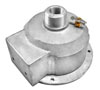
D0087 
D0062 
Lower Housing D0056 
D0088 
D0063 
Upper Housing D0054 
D0058 
D0061 
Diaphragm D0107 
D0104 
Mounting Bracket D0303 
Diaphragm Plate (2 Req’d) D0003 
1-½” Locknut D0127-A 
D0127-A D0127-A Connecting Rod Assembly D0050 
D0050 D0051 
Fulcrum Eyebolt D0004 
D0004 D0004 Check Valve D0340 
D0340 D0340 Drain Cock D0347A 
D0347A D0347A Fast Pin Assembly (2 Req’d) X0D01 
X0D01 X0D01 Thumb Screw HANDLE ASSEMBLY – #D0047 HANDLE W/ GRIP ASSEMBLY – #D0095 PART # DESCRIPTION PART # DESCRIPTION D0093 Handle Bracket (Includes 2 Fast Pins & Thumb Screws) D0094 Grip D0095 Handle w/ Grip Assembly (See Right) D0094-5 Handle (Pipe) 

OLD STYLE PARTS (Available Upon Request) OLD STYLE DP5 & DP7 OLD STYLE DP9 PART# PART DESCRIPTION PART# PART DESCRIPTION D0339 
Ball Check Valve D0001 
Fulcrum Bracket (Old DP9) D0300 
Valve Bushing D0129 
Fulcrum Link (2 Req’d) Optional REPAIR KITS
#D05RK (DP5), D07RK (DP7), D09RK (DP9)PART# DESCRIPTION PART# DESCRIPTION D0004 Check Valve (Disk) X0D04 ¼”-20 x 1″ Bolt
(4 Req’d)D0054, D0058, D0061 Diaphragm X0D08 ³/8″ Internal Tooth Lock Washer D0303(DP5 only) Diaphragm Plate X0D09 ¼” Split Lock Washer
(4 Re’q)D0340 Drain Cock X0D10 ³/8″ Flat Washer X0D03 ¼”-20 Hex Nut (4 Re’q) X0D11 ³/8″-16 Hex Nut
(2 Req’d)
Motorized Diaphragm Pump
Motorized Diaphragm Pump
download product catalogueTHE Motorized Diaphragm Pump (MDP) is a fulcrum actuated pump. It pumps water, brine, mud sewage, petroleum products and many chemicals. This versatile pump comes in several models: HP700EF, HP700G, and the HP700DC. They are low maintenance units. Electric models are 1-HP, specify: 1 Phase, 3 Phase or 12 volt DC direct.
MOTORIZED DIAPHRAGM PUMP FEATURES
Self-priming MDPs can run dry without damage to the pump seal.
The natural rubber compound diaphragm is strong and long lasting.
Easy to replace valves.
Steel base for secure mounting.
HP700 E & G can be equipped with a carrying bar.
Units range from 26-32 GPM.
-
INSTALLATION & OPERATION
- Determine pump location and, if desired, secure in place (5/16″ bolts recommended).
- Connect suction hose or pipe to suction flange.
- If desired, connect discharge hose or pipe.
- Connect power source (electric models).
- Start pump; may be operated indefinitely.
-
SAFETY & RECOMMENDATIONS
- To extend diaphragm and valve life, flush the pump with water after each use.
- Replace the diaphragm and valves that show signs of wear, cracking or corrosion.
- For AC models: make sure electrical connection is properly grounded.
- Keep clear of rotating and reciprocating components.
- If pumping liquid other than water, flush thoroughly with water after use.
-
Oil Centrifuge Machine Parts
HP700G HP700EF PART# PART PART# PART DESCRIPTION H0374 
H0385 Connecting Rod H0375 
H0375 Rod End Bearing H0380 
H0384 Crank Disc H0388 Diaphragm Mounting Block H0701 
H0701 Pump Body H0703 
H0703 Retainer Ring H0704EF 
Fulcrum H0707C NEO 
H0707C NEO Diaphragm (Neoprene) H0709 
H0709 Diaphragm Plate (2 Req.) H0710 NEO 
H0710 NEO Discharge Valve H0714 NEO 
H0714 NEO Suction Valve H0902 Fulcrum Pin H0905 
Additional Suction Flange H0905 H0905 Suction Flange H0906 
H0906 Discharge Flange (2 Req. for HP700EF) P0015-700 (no image available) H0732 (no image available) Base * (No Image
Available)H0730 (no image available) Gear Reducer
Exhaust Primer
Exhaust Primer
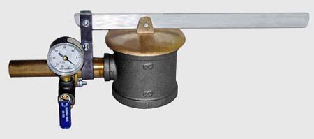
download product catalogueExhaust Primers (EP) are comprised of an Ejector and cast iron Adapter that has a cap and handle attached. Unit operates on low engine exhaust pressure. When exhaust valve (adapter cap) is closed, gases are directed through ejector, and water is drawn to pump by ejector vacuum.
*Note: When ordering an EP, ejector size is determined by engine displacement in cubic inches.
Example: displacement is 250 cubic inches; therefore you need an EP250-300. Adapter size is determined by size of exhaust tip and whether it is threaded or not.
EXHAUST PRIMER FEATURES
Simple design, no moving parts.
Cast iron adapters come in a variety of sizes, to be mounted on a plain or threaded exhaust ends.
Priming can be completed in 10 seconds to two minutes.
Suction lifts of 20 ft. may be obtained under typical conditions.
Units are designed to produce vacuum of 18 to 22 inches of mercury (Hg).
Normal speeds for small engines are usually higher than for large engines, therefore primers may be generally classified in four groups as follows:
-
INSTALLATION & OPERATION
- Use adapter to attach ejector to engine exhaust stack.
- Pump discharge must be closed while priming. This can be done by installing a discharge check valve or hand operated gate valve.
- Install vacuum gauge and priming valve on priming line, between the valve and ejector.
- After priming is completed, lay handle and brass cap 180 degrees from priming position to allow exhaust to escape.
*NOTE: Vacuum gauge should indicate priming rate of 18-22 Hg.
-
MAINTENANCE
- Before every use, check the unit for accumulated build-up of dirt or soot from the engine exhaust.
- If vacuum gauge is not working, replace before using EP.
-
SAFETY & RECOMMENDATIONS
- EPs will not work effectively on single cylinder or two cycle (two strokes) engines.
- Installing a Tachometer on the engine to determine exact speed is useful.
- Line air leaks may prevent priming.
- EPs can be used on turbo engines, provided that the RPMs are kept between 1100 and 1200.
- This information is set forth in general terms for the benefit of distributors, but it is advisable that distributors provide appropriate instruction to their customers.
-
Exhaust Primer – Parts
STANDARD PARTS PART# DESCRIPTION *Ejector (See chart on right for part numbers) *Exhaust Valve (See chart on right for part numbers) *Adapter (See chart below for part numbers) E0008 ³/8 X ³/8 X ¼
Priming Tee
E0022 Clamp 
E0323 Handle for Brass & Steel Caps 
E0333 Vacuum Gauge 
E0334 ⅜” FPT
Brass Cock Valve
X0E17 ⅜” NPT x 1”
Close Nipple
EJECTORS PART# DESCRIPTION E0090 60/90 Ejector 
E0091 150/225 Ejector 
E0092 250/300 Ejector 
E0093 350/500 Ejector 
ACCESSORIES PART# DESCRIPTION X0D03 Hex Nut/td> X0D04 ¼ -20 x 1″ Bolt X0D09 ¼ ” Split Lockwasher X0E12 10-24 x ½ ” Machine Screw (60/90 only) X0T27 ¼ #18 Internal Tooth Lockwasher EJECTORS PARTS Venturi Gasket Nozzle Tip Nozzle Base 60/90  E1379
E1379 E0315
E0315 E1369M
150/225  E2715
E2715 E2315-A
 E2315
E2315250/300 E2925 E2315-BE2315
350/500  E1384
E1384 E0141
E0141 E3940C
ADAPTERS PART# DESCRIPTION E0000 1″ Adapter 
E0001 1 ¼” Adapter E0002 1 ½” Adapter E0003 2″ Adapter E0004 2 ½” Adapter E0005 3″ Adapter E0006 3 ½” Adapter E0007 4″ Adapter EXHAUST VALVES PART# DESCRIPTION E0014 1 ¾” Brass 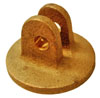
E0317 2 ¼” Brass 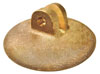
E0318 2 ¾” Steel 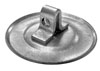
E0015 2 5/8″ Brass 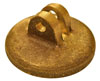
E0016 3 ¼” Brass 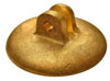
E0017 4 ¹/16″ Brass 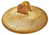
E0018 5″ Brass 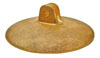
Hand Diaphragm Pump
Hand Diaphragm Pump
download product catalogueTHE Hand Diaphragm Pump (HP) is a single-chamber air and liquid pump. The chamber has 2 opening flapper valves for suction and discharge. The diaphragm is actuated by the fulcrum handle bracket, air and/or liquid is pulled into the chamber through the suction valve and expelled through the discharge valve.
HAND DIAPHRAGM PRIMER FEATURES
Lightweight, durable and portable.
Ideal for priming pumps or as portable pump.
Large inlets allow transfer of many types of liquids.
Upon request, unit can be provided with a wooden base to optimize stability for tough primes.
Easily delivers up to 30 GPM.
Maximum leverage design facilitates easier pumping.
-
INSTALLATION & OPERATION
- Insert handle into fulcrum, making sure that fulcrum and handle holes align before inserting the fulcrum pin.
- Place pump on a solid foundation that is as close as possible to the fluid that is going to be pumped. (This positioning should make the suction line as short and direct as possible.)
- Attach suction pipes to the suction inlet and to the discharge outlet.
- Suction line must be sloped upward in order to provide continual feed into the pump.
-
SAFETY & RECOMMENDATIONS
- To extend diaphragm and valve life, flush the pump with water after each use.
- Replace the diaphragm and valves that show signs of wear, cracking or corrosion.
-
Hand Diaphragm Pump – Parts
DIAPHRAGM ASSEMBLY – #H0707 & H0907 PART# DESCRIPTION H0707C/H0907C Diaphragm H0709 Galvanized Steel Plate (2 Req.) X0019 Eyebolts w/ Nuts 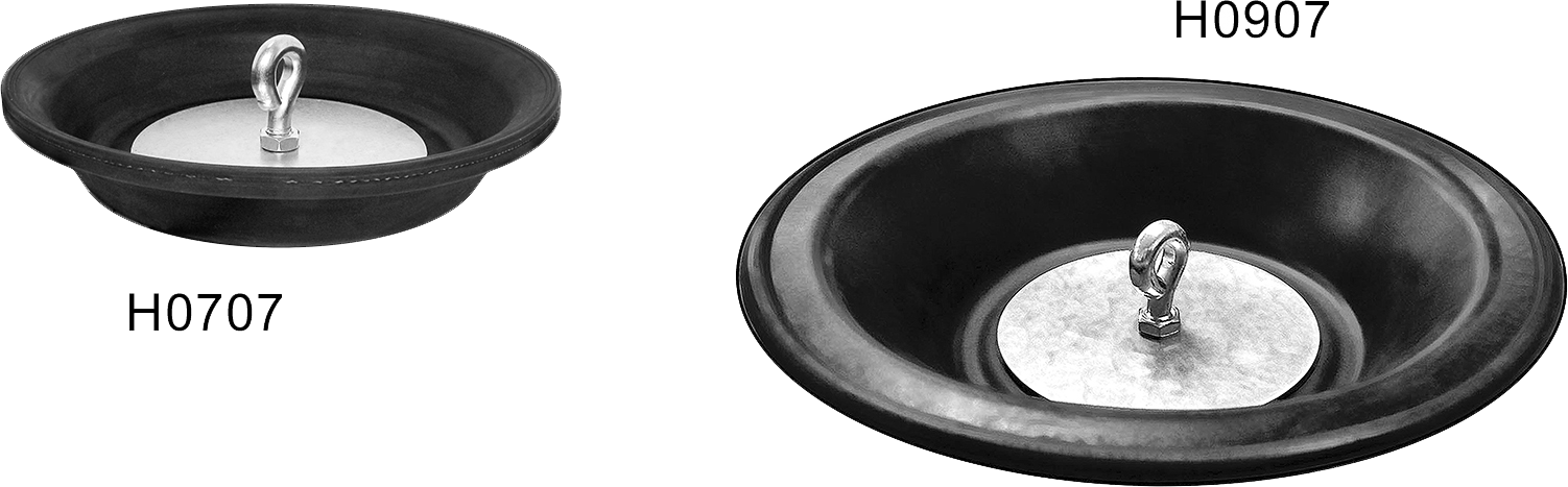
HANDLE ASSEMBLY – #H0912 PART# DESCRIPTION H0712 Grip H0911 Handle 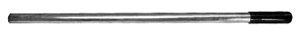
HP700 PARTS HP900 PARTS DESCRIPTION H0701 
H0901 Pump Body H0902 
H0902 Fulcrum Pin H0703 
H0903 
Retainer Ring H0704 
H0704 
Fulcrum H0705 
H0905 
Suction Flange H0706 
H0906 Discharge Flange H0707C 
H0907C 
Diaphragm H0709 
H0709 Diaphragm Plate (2 Req’d) H0710 NEO 
H0910 
Discharge Valve H0714 NEO H0910 Suction Valve D0347A 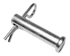
D0347A Fast Pin Assembly X0019 
X0019 Eyebolt Assembly X0D01 
X0D01 Thumbscrew REPAIR KITS HP7RK HP9RK DESCRIPTION H0707C H0907C Diaphragm H0709 H0709 Diaphragm Plate (2 Req.) H0710 NEO H0710 NEO (2 Req.) Discharge Valve (Also Suction Valve for HP900) H0707C H0907C Diaphragm H0714 NEO – Suction Valve (HP700/HP7RK Only) D0347A D0347A Fastpin H0902 H0902 Fulcrum Pin X0019 X0019 Eyebolt Assembly X0D11 X0D11 ³/8-16″ Jam Nut (2 Req.) X0H21 X0H21 5/16-18″ x 2″ HH Bolt (4 Req.) X0H31 X0H31 5/16-18″ x 1″ HH Bolt (8 Req.) X0H41 X0H41 5/16-18″ Nut (4 Req.)
-
Pumps
-
Primers
-
Oil Field