

Blog
Hand Diaphragm Primer
Posted by admin

-
INSTALLATION & OPERATION OF HAND DIAPHRAGM PRIMER PUMP
- Attach mounting bracket to centrifugal pump or skid.
- Use non-collapsible hose or flexible tubing to connect primer suction inlet to pump.
- Install cut-off valve between the primer suction inlet and pump.
- Close cut-off valve immediately after priming.
- Make sure primer drain valve is closed.
- A cut-off valve should be used at the pump discharge to prevent air from being drawn through the discharge line while priming.
-
MAINTENANCE
- Remove any debris under the diaphragm after each use.
- Clear all fluids from inside the unit after each use.
-
TROUBLESHOOTING
If DP is not priming the pump, check the following: - Make sure drain cock is closed.
- Inspect check valve for blockage and free movement.
- Check suction side for air leaks.
- Call Protek Technical Support for additional help.
-
Hand Diaphragm Primer – Parts
DP5 DP7 DP9 Description D0055 
D0087 D0062 Lower Housing D0056 D0088 D0063 Upper Housing D0054 D0058 D0061 Diaphragm D0107 D0104 Mounting Bracket D0303 Diaphragm Plate (2 Req’d) D0003 1-½” Locknut D0127-A D0127-A D0127-A Connecting Rod Assembly D0050 D0050 D0051 Fulcrum Eyebolt D0004 D0004 D0004 Check Valve D0340 D0340 D0340 Drain Cock D0347A D0347A D0347A Fast Pin Assembly (2 Req’d) X0D01 X0D01 X0D01 Thumb Screw HANDLE ASSEMBLY – #D0047 HANDLE W/ GRIP ASSEMBLY – #D0095 PART # DESCRIPTION PART # DESCRIPTION D0093 Handle Bracket (Includes 2 Fast Pins & Thumb Screws) D0094 Grip D0095 Handle w/ Grip Assembly (See Right) D0094-5 Handle (Pipe) OLD STYLE PARTS (Available Upon Request) OLD STYLE DP5 & DP7 OLD STYLE DP9 PART# PART DESCRIPTION PART# PART DESCRIPTION D0339 Ball Check Valve D0001 Fulcrum Bracket (Old DP9) D0300 Valve Bushing D0129 Fulcrum Link (2 Req’d) Optional REPAIR KITS
#D05RK (DP5), D07RK (DP7), D09RK (DP9)PART# DESCRIPTION PART# DESCRIPTION D0004 Check Valve (Disk) X0D04 ¼”-20 x 1″ Bolt
(4 Req’d)D0054, D0058, D0061 Diaphragm X0D08 ³/8″ Internal Tooth Lock Washer D0303(DP5 only) Diaphragm Plate X0D09 ¼” Split Lock Washer
(4 Re’q)D0340 Drain Cock X0D10 ³/8″ Flat Washer X0D03 ¼”-20 Hex Nut (4 Re’q) X0D11 ³/8″-16 Hex Nut
(2 Req’d)


Nov 25 2015
Motorized Diaphragm Pump
Posted by admin
-
INSTALLATION & OPERATION
- Determine pump location and, if desired, secure in place (5/16″ bolts recommended).
- Connect suction hose or pipe to suction flange.
- If desired, connect discharge hose or pipe.
- Connect power source (electric models).
- Start pump; may be operated indefinitely.
-
SAFETY & RECOMMENDATIONS
- To extend diaphragm and valve life, flush the pump with water after each use.
- Replace the diaphragm and valves that show signs of wear, cracking or corrosion.
- For AC models: make sure electrical connection is properly grounded.
- Keep clear of rotating and reciprocating components.
- If pumping liquid other than water, flush thoroughly with water after use.
-
Oil Centrifuge Machine Parts
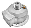
HP700G HP700EF PART# PART PART# PART DESCRIPTION H0374 H0385 Connecting Rod H0375 H0375 Rod End Bearing H0380 H0384 Crank Disc H0388 Diaphragm Mounting Block H0701 H0701 Pump Body H0703 H0703 Retainer Ring H0704EF Fulcrum H0707C NEO H0707C NEO Diaphragm (Neoprene) H0709 H0709 Diaphragm Plate (2 Req.) H0710 NEO H0710 NEO Discharge Valve H0714 NEO H0714 NEO Suction Valve H0902 Fulcrum Pin H0905 Additional Suction Flange H0905 H0905 Suction Flange H0906 H0906 Discharge Flange (2 Req. for HP700EF) P0015-700 (no image available) H0732 (no image available) Base * (No Image
Available)H0730 (no image available) Gear Reducer


Nov 24 2015
Hand Diaphragm Pump
Posted by admin
-
INSTALLATION & OPERATION
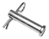
- Insert handle into fulcrum, making sure that fulcrum and handle holes align before inserting the fulcrum pin.
- Place pump on a solid foundation that is as close as possible to the fluid that is going to be pumped. (This positioning should make the suction line as short and direct as possible.)
- Attach suction pipes to the suction inlet and to the discharge outlet.
- Suction line must be sloped upward in order to provide continual feed into the pump.
-
SAFETY & RECOMMENDATIONS
- To extend diaphragm and valve life, flush the pump with water after each use.
- Replace the diaphragm and valves that show signs of wear, cracking or corrosion.
-
Hand Diaphragm Pump – Parts
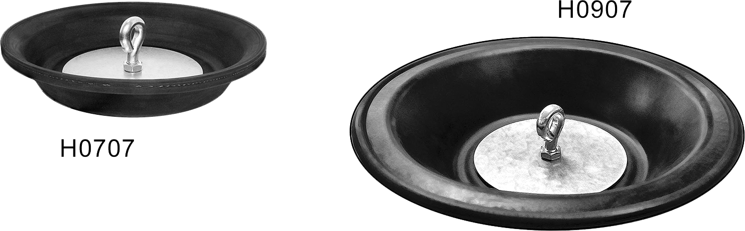
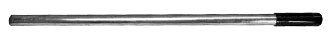
DIAPHRAGM ASSEMBLY – #H0707 & H0907 PART# DESCRIPTION H0707C/H0907C Diaphragm H0709 Galvanized Steel Plate (2 Req.) X0019 Eyebolts w/ Nuts HANDLE ASSEMBLY – #H0912 PART# DESCRIPTION H0712 Grip H0911 Handle HP700 PARTS HP900 PARTS DESCRIPTION H0701 H0901 Pump Body H0902 H0902 Fulcrum Pin H0703 H0903 Retainer Ring H0704 H0704 Fulcrum H0705 H0905 Suction Flange H0706 H0906 Discharge Flange H0707C H0907C Diaphragm H0709 H0709 Diaphragm Plate (2 Req’d) H0710 NEO H0910 Discharge Valve H0714 NEO H0910 Suction Valve D0347A D0347A Fast Pin Assembly X0019 X0019 Eyebolt Assembly X0D01 X0D01 Thumbscrew REPAIR KITS HP7RK HP9RK DESCRIPTION H0707C H0907C Diaphragm H0709 H0709 Diaphragm Plate (2 Req.) H0710 NEO H0710 NEO (2 Req.) Discharge Valve (Also Suction Valve for HP900) H0707C H0907C Diaphragm H0714 NEO – Suction Valve (HP700/HP7RK Only) D0347A D0347A Fastpin H0902 H0902 Fulcrum Pin X0019 X0019 Eyebolt Assembly X0D11 X0D11 ³/8-16″ Jam Nut (2 Req.) X0H21 X0H21 5/16-18″ x 2″ HH Bolt (4 Req.) X0H31 X0H31 5/16-18″ x 1″ HH Bolt (8 Req.) X0H41 X0H41 5/16-18″ Nut (4 Req.)


Nov 19 2015